Adjusting the MEC Reloading Machine
By Don Keller
November 16, 2008
Forward:
The purpose of this document is to have both New and Old shooters understand the mechanical structure of MEC Reloading machine. Individuals will be able to make all the necessary adjustments, allowing them to determine if something is wrong and how to correct any problem. After making the appreciate adjustments, one can get back to reloading and having fun.
Tools required:
1-Screwdriver
1-7/16" wrench
1-1 / 2" wrench
1- Alan wrench to fit the screws in the front of the machine
1- Tool Shell (See Picture 1 Below)
CutShell Reloader Primer
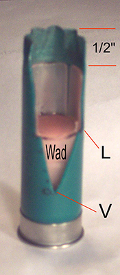
How to make an important "Tool Shell:"
Take a spent shell and cut a "V" in the side of it. Than take a wad and cut one of the four sides off. Insert the wad on station # 3. Try to keep the cutout in line with the V in the shell. Remove the shell from the machine. Now measure ½" from the top of the wad up to the edge of the crimp. Now cut a n "L" shape notch on both sides of the "V". at the level of the floor of the cup. This tool is used to set up station # 3.
This method works for all gauges:
12 Ga. ½"
16 Ga. ½"
20 Ga. 3/8"
28 Ga. ¼"
Getting your machine ready to make adjustments:
Remove the following from the machine:
All shells
Both bottles
On machines with a self advancing carrier. Remove the arm. You will move the carrier when necessary.
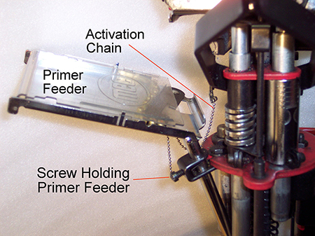
Primer Feeder:
Remove the primer feeder from the machine. You should polish the slide using car wax. This will make the primers glide over the surface.
Replacement of the feeder:
Push the handle down and slide the tube into the hole. Let the tube rest on the carrier. Snug the holding screw. Now look closely at the carrier to see if the tube of the feeder aligns with the hole in the carrier. The angle of the tube needs to be level with the carrier. Test your feeder by removing the piston from station #2 and place your tray under the opening. Test this stage for alignment.
Station # 1
De-priming and seizing:
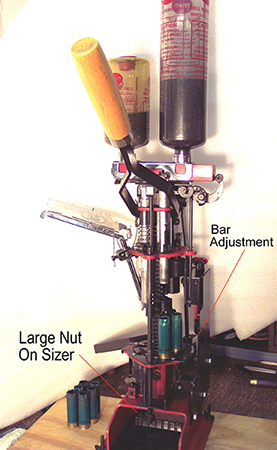
On new machines, to adjust the seizer, turn the large nut to the right to make it smaller. There is no adjustment on the punch.
On older machines, the length of the punch needs to be long enough to push the old primer out.
It also needs to push the shell out of the sizing die when you use it. When using the sizing die you will need to remove the primer feeder to screw in the die.
NOTE: When adjusting station 2 & 3, tip the bar back and remove the two tubes. This will give you room to make the adjustments.
Station # 2
Priming:
To adjust this tube, first loosen the alan screw near the top of the tube. (See picture 2 above) Make the tube ½" longer. Just using the shaft from this part of the station hold the shaft upright in your left hand, in its normal position, and lower the tube by pushing downward on the handle of the press. The tube will move upward as it touches the top of the shaft. Make sure you push the handle down all the way. Allow the handle to move up and tighten the alan screw. Reassemble the station.
Now (with the bar in place and your left hand on top of the bar for added weight) push the handle down slowly. The bar should lock. If the bar does not lock, you need to adjust the pull on the rod. (See picture 3 above). With the handle down, turn the nut counter clockwise. This will move the bar to the left. The bar should lock. To see if it unlocks, place a shell in the station and lower the handle. The bar should unlock and move to the right.
Station # 3
Inserting the Wad:
The length of this tube is determined by the Wad size you are going to use. Using the Shell Tool makes this adjustment easy. With the Shell Tool pre set ½", place the Shell Tool in station #3. Now lower the tube by pushing down on the press handle observing the tube inside the shell. With the handle down tap the top of the tube down so the tube touches the floor of the cup. Snug the alan screw. Check it before tightening.
Adjusting the wad guide:
Loosen the alan screw and swing it out out. Check the guide for any broken fingers or missing fingers. Swing it back and lower the tube. The guide will center it self. On older machines there is no clip to determine its height, so set it this way. Place a wad in the guide and allow the tube to be inside the cup 1/8". The wad will standup by it self. Make sure to center the guide before tightening.
Station # 4
Starting the Crimp:
With all gauges the crimp should look like a teepee, with the top open. On new machines the height can be adjusted. On older machines make sure the starting die can move freely. The die unscrews so it can be changed from a six to an eight point crimp.
With new machines just pop off the six point and snap on the eight point die.
Station # 5
Closing the Crimp
The depth of the crimp on a 12 GA. is 1/16". To make this adjustment you need to get your machine ready to load. Make sure to lock the bar and replace the tubes. To adjust, loosen the nut and turn the screw clockwise to deepen the crimp. If the crimp is too deep the center will have a hole in it. Make this adjustment slowly a ¼" turn of the screw for each shell you load. Be sure to tighten the nut after each adjustment. For other gauges look at the new shells and try to make them look the same.
Station # 6
Rounding or Deepening the Crimp
" DO NOT LOAD WHILE ADJUSTING THIS STATION "
If you shoot a pump or auto, this station is a must. To adjust, loosen the nut above the round die. Turn it up two full turns. Now loosen the other nut and turn it up. Place a shell in the station and lower the handle of the press. Turn the screw down until it touches the crimp. Snug the nut, turn the die down until it starts to round over the crimp. Lock the nut. You can now start to adjust for rounding off the crimp. Loosen the upper nut and turn the screw down a ¼ of a turn. Change shells as you adjust. Don't put too much pressure on the shell, as the walls of the shell can be deformed.
Adjustments for auto advancing carriers:
Should the carrier move beyond the normal locking position adjust the pull on the arm. Make sure the carrier is always in the correct position.
Trouble Shooting Tips
When something goes wrong stop and clean up the mess. All the shot spilled must be removed from the machine. Make sure the carrier moves freely. Use a brush to carefully remove all shot and powder from the carrier. Remember never put excessive pressure on the handle of the press. This only gives more trouble in getting the machine to work correctly.
Oiling the reloader:
Use a light oil as 3 in 1. A tissue under the part that requires oil keeps the oil from running all over the place. Oil all moving parts. The machines with a seizer (like the Grabber) oiling the key-way in the back side of the square shaft is a must. Oil the press 3 to 4 times each year.
Bar goes out of adjustment:
Should the bar go out of adjustment after a short period of time. Place a lock nut against the first nut locking the two together solves the problem for a long time.
Damaged, Broken or Missing Guide Fingers:
If a shell shoots properly but "sounds funny", one cause could be a damaged, broken or missing finger from the guide. When reloading, the tube pushes the wad through the guide into the shell. With a damaged or missing finger in the guide, the wad may catch and be inserted crooked. As the powder is burned some of the gas may bypasses the wad. This gives the abnormal sound and very poor performance of the shell.
Damp storage:
De-prime all hulls quickly if they are stored in a damp place. Primers can rust and make them hard to remove.
NOTE: It is ALWAYS BEST to store spent hulls in a clean dry place. As with all ammunition, it is also advised to keep them away from small curious hands.
Should you desire to have a manual on any model MEC reloading equipment:
Visit their web site: www.mecreloaders.com where you may download free copies of reloading equipment and process manuals.
Paper copies of manuals and publications may also be purchased at a current price of $5.00 each.
Tech. Support may be reached by telephone calling 800-797-4632 or by email addressed to: This email address is being protected from spambots. You need JavaScript enabled to view it.
Sales Support may be reached by telephone calling 920-387-4500 or sending a fax to 920-387-5802.
U.S. Postal service mail can be used to reach them at:
Mayville Engineering Co. Inc
715 South Street
Mayville, Wisconsin 53050